Schooner Goleta
Contact Seller
XPresented For Sale By:
Barcos Nautica
Spain
| Make | Schooner |
|---|---|
| Model | Goleta |
| Year | 2014 |
| Condition | Used |
| Price | US$14,900,000 |
| Type | Sail |
| Class | Cruiser (Sail) |
| Length | 172 ft |
| Fuel Type | Diesel |
| Hull Material | Other |
| Location | buenos aires, Argentina |
| LOA | 172 ft 5 in |
|---|---|
| Beam | 28 ft 5 in |
| Max Draft | 12 ft 6 in |
| Fuel Type | Diesel |
|---|
| Builder | Astilleros Buquebus |
|---|---|
| Guest Heads | 8 |
Description
BArco en CARBONO, mas grande fabricado en America
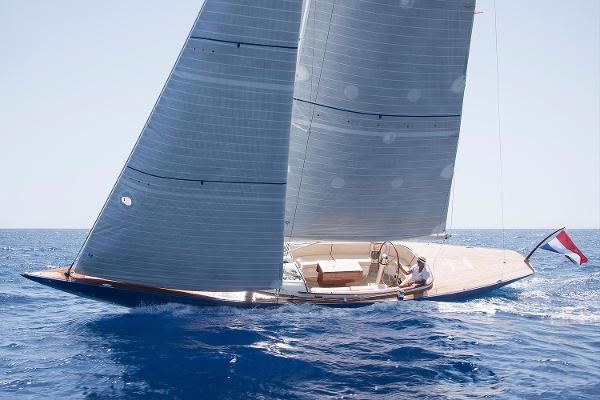
The largest carbon sailboat manufactured in America
Doña Francisca Yacht length 172´(52,43m) Build 2014/2024
Comentarios/ Comments
This is the construction of the largest yacht in Latin America, in carbon fiber,
This is the construction of a larger yacht in Latin America and the largest carbon fiber
A significant carbon fiber / epoxy infusion hull
An extraordinary carbon fiber hull with epoxy infusion yachts
Carbon was the material chosen for its construction, because among the benefits of this material is to increase the ballast / displacement ratio,
Carbon was the material chosen for its construction, because among the benefits of this material is to increase the ballast / displacement ratio,
The yacht is requested to be able to navigate in shallow waters, including the Río de la Plata.
The yacht is requested to be able to navigate in shallow waters, including the Río de la Plata
The keel is of type "T" with a very low center of gravity that helps keep your entire navigation plan.
The keel is of type "T" with a very low center of gravity that helps keep your entire navigation plan.
The mast is produced by King Composite. Due to their excellent results in the Germanischer Lloyd Certificate
Carbo-Link is currently the only carbon rigging manufacturer able to provide solid carbon cables up to working loads of 100 tons, making Carbo-Link the premier supplier of carbon rigging for superyachts.
The mast is produced by King Composite. Due to their excellent results in the Germanischer Lloyd Certificate, Carbo-Link is currently the only carbon rigging manufacturer able to provide solid carbon cables up to working loads of 100 tons making Carbo-Link the premier supplier of carbon rigging for superyachts.
19th century sailboat with 21st century technology
CURRENTLY IS A WHITE HELMET AND THE INTERIOR TEMPERATURE OF THE BOAT HAS BEEN DECREASED
19th century sailboat with 21st century technology
CURRENTLY IS A WHITE HELMET AND THE INTERIOR TEMPERATURE OF THE BOAT HAS BEEN DECREASED
Your electronics is the latest generation for navigation.
The schooner began to be built four years and three months ago, recalled its owner (February 1, 2015)
The boat is the synthesis of the best naval architecture that combines marine excellence with absolute perfection in terms of comfort for the owner and his sailors.
The carbon fiber rigs allow to save a ton and a half of weight in comparison with those made on the basis of more conventional materials.
For the construction of the helmet, he had to obtain an authorization from the United States government for the purchase of carbon fiber.
Timber: Teak and Walnut
Your electronics is the latest generation for navigation.
The schooner, began to be built four years and three months ago, recalled its owner (February 1, 2015)
The boat is the synthesis of the best naval architecture that combines marine excellence with absolute perfection in terms of comfort for the owner and his sailors.
The use of modern elements allows the boat to save weight.
The carbon fiber rigs allow to save a ton and a half of weight in comparison with those made on the basis of more conventional materials.
For the construction of the helmet, he had to obtain an authorization from the United States government for the purchase of carbon fiber.
Spanish company manufactures part of the roof hatches in carbon, as well as the rigging of labor and its design in collaboration with Italian company
Its installation is flush and adjusted to the curvature of the roof
The 3D design, the molds by numerical control, laminated by infusion and curing in a special oven.
They are also designers of the fixed and working rigging: halyards, sheets, coarse.
The main sail sheet has a workload of 16 tons and the Genoa of 15 tons
Extras
Length Over All: 52.50m / 172.24 feet. Including your bow boom
Length On Deck: 45.80m / 150.22 feet
Length water line: 39.00 m / 127.92 feet
Beam: 8.67m / 28.43 Feet
Draught: 3.81m / 12.50 Feet
Displacement dry: 206 Tn.
Ballast: 62 Tn.
Relation: 30.09 %
Sailplan: Bermuda Schooner (1,084m²)
Standing Rigging: Carbo-Link (Switzerland)
Foremast: 48.98m, King Composite (Argentina)
Mainmast: 50.99m, King Composite (Argentina)
Foremast furling boom: 14.00m, King Composite (Spain)
Mainmast furling boom: 16.50m, King Composite (Spain)
Bowsprit: 10.00m
Loft: Doyle Sails (New Zealand)
Fuel Tank: 15,940 Lt.
Drinking Water: 5,140 Lt.
Architect Design Javier Soto Acebal
Exterior e Interior Design Soto Acebal
EXTRAS
2 Generators CATERPILLAR C 4.4 of 45 KW
Minimum Nominal Value 36R ekW (45 kVA)
Maximum Nominal Value 99 ekW (123 kVA)
Frequency 50 or 60 Hz.
Sail Rollers BAMAR Hydraulic furlers: GFI 50 #195; GFI 35 #150
Roller Furling BAMAR
Electrical Design and Monitoring System VCAM "CERVINA"
Electrical Design and Monitoring System VCAM "CERVINA"
Built under certifications of RINA homologation office
Built under certifications of RINA homologation office
Acomodation
See cabin distribution plan
See Layout
Guest 8
cabins 4
Crew 7
The owner's cabin, aft, has 36 square meters.
This has a fully operational adjacent office.
To the bow is the hall, which extends the full width of the ship. There is a seating area and opposite it is a dining table, with capacity for ten people, comfortably installed.
Following, forward, On each band, 2 cabins with two beds with bathroom
More bow, on port, cabin with two bunk beds overlapping with bathroom
To starboard kitchen
It follows to port: breakfast area and meals crew
To starboard, cabin with double bed with bathroom, for Captain
And in the bow two cabins with bunk beds on top, with their respective bathrooms
Velas/ Sails
Genoa: 424 m2 GENOVA
Main Sail: 334 m2 MAYOR
Jib: 254 m2 FOQUE
Electronica/ Electronic
MOTOR
CATERPILLAR C 18
Power: 803 HP with 220 Hours.
Min.: 803 ch (803 hp)
Max.: 1136 ch (1136 hp)
Extra information 1
GENERAL GUIDANCE AND ADMINISTRATION
GENERAL GUIDANCE AND ADMINISTRATION
Classification
Certified under RINA classification.
RINA Pleasure Yachts
Hull Malta Cross
Special note: GREEN STAR PLATINUM
Classification
Certified under RINA classification.
RINA Pleasure Yachts
Hull Malta Cross
Special note: PLATINUM GREEN STAR
CLASS NOTATIONS - RINA
CONSTRUCTION RULES - RINA
Main Class Symbol MAIN CLASS SYMBOL
Except for special cases, class is assigned to a ship only when the hull, propulsion and auxiliary machinery installations, and equipment providing essential services have all been reviewed in relation to the requirements of RINA’s Rules.
With the 5 year class period is to be understood as being the highest class granted by the Society.
Except in special cases, class is assigned to a ship only when the hull, propulsion and auxiliary machinery installations, and equipment providing essential services have been reviewed in relation to the requirements of RINA’s Rules.
With the 5 year class period is to be understood as the highest class granted by the Society.
Construction Marks CONSTRUCTION MARKS
The construction mark identifies the procedure under which the yacht and its main equipment or arrangements have been surveyed for initial assignment of the Class.
The construction mark identifies the procedure under which the yacht and its main equipment or arrangements have been surveyed for initial assignment of the Class.
Construction marks defined below are assigned separately to the hull of the yacht and its appendages, to the machinery installation.
Construction marks defined below are assigned separately to the hull of the yacht and its appendages, and to the machinery installation.
The construction mark is placed before the symbol HULL for the hull, before the symbol MACH for the machinery installations, and before the additional Class Notation granted, when such a notation is eligible for a construction mark.
The construction mark is placed before the symbol HULL for the hull, before the symbol MACH for the machinery installations, and before the additional Class Notation granted, when such a notation is eligible for a construction mark.
When the same construction mark is assigned to both hull and machinery, the construction mark is assigned globally to the ship without indication HULL and MACH after the main class symbol.
When the same construction mark is assigned to both hull and machinery, the construction mark is assigned globally to the ship without indication HULL and MACH after the main class symbol.
Hull Construction Mark (HULL) Hull Construction Mark (HULL) RULES
✠ MALTA CROSS
Construction mark ✠ is assigned to the hull, when it has been surveyed by RINA during its construction in compliance with the new building procedure.
The construction mark ✠ is assigned to the hull, when RINA has inspected it during its construction in accordance with the new building procedure.
HULL STRUCTURE
General
Hull and Deck are sandwich construction, vacuum consolidate and resin infused with postcured at 45 degrees C. Both hull deck and all structures are made of carbon fiber (Sigmatex, USA) with epoxy resin (Resoltech, France), and its core is Divinycell (Diab, USA) Glass fibre has been used nearby the keel and shaft line for cathodic protection.
The hull and deck are sandwich construction, vacuum consolidated and resin infused with post-cured at 45 degrees C. Both hull deck and all structures are made of carbon fiber (Sigmatex, USA) with epoxy resin (Resoltech, France), and its core is Divinycell (Diab, USA). Glass fiber has been used near the keel and shaft line for cathodic protection.
TANKS CAPACITY
Fuel Tanks: 15,940 Lt.+ 1,057 Lt. On day tank The day tank
Fresh Water Tanks: 5,140 Lt.
Black and Grey Water tanks: 4,709 Lt.
SPECIAL PURPOSE SYSTEMS
SPECIAL PURPOSE SYSTEMS
Keel The keel is composed by a hydrodynamic steel blade and lead casting bulb made of lead and antimony alloy.
KEEL - The keel is composed of a hydrodynamic steel blade and a lead casting bulb made of lead and antimony alloy.
PROPULSION PLANT
ENGINE ROOM GENERAL
Machinery Room
PROPULSION PLANT
GENERAL ENGINE ROOM
Machinery Room
The following is located in the engine and/or pumps room:
-One (1) Diesel propulsion engine Caterpillar C18 Acert 803hp with reduction & variable pitch gear Hundested CPG 32-Two (2) Generator sets Caterpillar C4.4 50kw each-Auxiliary machinery necessary for the function of the ship services-Exhaust gas piping for the main and auxiliary propulsion engines and the ventilation devices brand Gianneschi-Watermaker Spectra Farallon 2800-Sewage Treatment Plant HMSA-Air-Conditioner central unit Dometic Marine Air 216000BTU-Hydraulic Unit composed of reservoir and electric pump-Bilge filtering System RWO S Debit-Bilge and Firefighting pumps Gianneschi-Fresh Water pressure and filtering systems Gianneschi-One 250 liter boiler plus one 80 liter boiler both Gianneschi-Compressor Gianneschi-24, 220 and 380V Panels-Inverters -Other electrical devices
The following is located in the engine and/or pumps room:
One (1) Diesel propulsion engine Caterpillar C18 Acert 803hp with reduction and variable pitch gear Hundested CPG 32
Two (2) generator sets Caterpillar C4.4 50kw each
Auxiliary machinery necessary for the function of the ship services
Exhaust gas piping for the main and auxiliary propulsion engines and the ventilation devices brand Gianneschi
Watermaker Spectra Farallon 2800
Sewage Treatment Plant HMSA
Central air conditioning unit Dometic Marine Air 216000 BTU
Hydraulic Unit composed of reservoir and electric pump
Bilge filtering System RWO S Debit
Bilge and Firefighting pumps Gianneschi
Fresh Water pressure and filtering systems Gianneschi
One 250 liter boiler plus one 80 liter boiler both Gianneschi
Compressor Gianneschi
24, 220 and 380V Panels
Inverters - Other electrical devices
Entrances and Exits Access to engine room through Water and gas tight doors brand Freeman, USA. Access to deck through two big size hatches one on each side.
Openings for Engine Removal The engine room ceiling has a dismountable panel of a suitable dimension to allow the passage of the main propulsion engine.
Entrances and exits Access to the engine room through water and gas tight doors brand Freeman, USA. Access to the deck through two large hatches, one on each side.
Openings for engine removal The ceiling of the engine room has a removable panel of a suitable size to allow the passage of the main propulsion engine
PROPULSION INTERNAL COMBUSTION ENGINES
PROPULSION INTERNAL COMBUSTION ENGINES
Main Engine Characteristics Caterpillar C18 ACERT 803 hp
Reduction Gear Hundested CPG 32 - 3.96:1
Main engine characteristics Caterpillar C18 ACERT 803 hp
Reduction Gear Hundested CPG 32 - 3.96:1
TRANSMISSION AND PROPULSOR SYSTEMS
TRANSMISSION AND PROPULSOR SYSTEMS
PROPULSION Shaft Line
Propulsion. Shaft line
Hundested VP 91/2 HP/HP 1400mm diameter 4 blade Propeller made of Ni-Al-Bz651 HP @556RPM. Hundested Shaft 1.4404. Outside diameter 130mm, inside diameter 40mm
Hundested VP 91/2 HP / HP 1400mm diameter 4 blades Propeller made of Ni-Al-Bz651 HP @ 556RPM. Hundested Shaft 1.4404. Outside diameter 130 mm, inside diameter 40 mm
" src="cid:[email protected]" alt="Description: Hundested Propeller A/S" width="202.5" class="Apple-web-attachment"> VP Propellers Variable-pitch propeller
Variable pitch propeller
Main Engine Controls
Main engine controls
The engine control panel is placed at the steering external station, starboard side. Engine control includes:-Stop push button-Start push button-Morse cable control-Variable pitch control
The engine control panel is located at the external steering station, starboard side.
The engine control includes:
Stop, Push the button
Start, Push the start button
MORSE cable control
Pitch angle control
Main Engine Monitoring and Alarm Panel
Main engine monitoring and alarm panel
Steering station monitoring panel to include:-Start contact-Revolutions Counter-Voltmeter-Cooling Water Temperature-Engine Oil Pressure-Engine Water Temperature-Pitch Indicator
The monitoring panel of the steering station includes:
- Start contact
- Revolutions count
- Voltmeter
- Heating of water temperature
- Engine oil pressure
- Engine water temperature
- Pitch angle indicator
Engine Room Panel to include:-Start contact-Engine Stop
Engine room panel includes:
- Engine Start
- Stop Engine
Main Engine Alarm Panel
Main engine alarm panel
Sound and visual alarm panel to include:-Engine Water Temperature-Engine Oil Pressure-Engine Batteries Charging
Sound and visual alarm panel includes:
- Engine water temperature
- Engine oil pressure
- Engine battery charging
CIRCULATING AND COOLING SEA WATER SYSTEM
Engine sea water cooling system
System:-Intake of seawater to be from main sea water manifold (see 163 sea chest)-Positive control valve is fitted on manifold-Outlet of cooling water to engine exhaust piping between the engine exhaust manifold and the acqua-lift silencer
CIRCULATING AND COOLING SEA WATER SYSTEM
Engine sea water cooling system
System:
The intake of seawater will be from the main seawater manifold (see 163 sea chest)
Exhaust System
The exhaust gas has cooling water injected after the engine exhaust manifold. Wetted gas runs to acqua-lift G.R.P. muffler. Water and gas runs to outlet fitting about 350mm above the waterline. The exhaust should be fitted nearby the stern. A goose neck loop is fitted between the muffler and the outlet fitting on hull.
Exhaust system
The exhaust gas has cooling water injected after the engine exhaust manifold.
The wetted gas runs to the acqua-lift G.R.P. silencer.
The water and gas run to the outlet fitting about 350 mm above the waterline.
The exhaust should be installed near the stern.
A goose neck loop is placed between the silencer and the outlet fitting on the hull.
Extra information 2
ELECTRIC PLANT
ELECTRIC PLANT
GENERAL ARRANGEMENT-ELECTRICAL DRAWINGS
GENERAL ARRANGEMENT-ELECTRICAL DRAWINGS
The correct working of the electrical system will be insured even during sailing up to 30º of heel. Intention of this project is to keep the number of cables to minimum and not to add weight to the vessel.
The correct functioning of the electrical system will be ensured even during navigation up to 30º of heel. The intention of this project is to keep the number of cables to a minimum and not to add weight to the vessel.
ELECTRIC CABLES
ELECTRIC CABLES
Wiring 1
Where feasible light weight cables will be used to reduce the weights. Wiring shall be of tinned stranded copper conductors PVC insulated (75º), with neoprene impervious sheathing, 95ºC or better. Cables shall be of the shielded type and adequately protected from mechanical damage and installed in accordance with the best marine practices. There shall be no wiring in the bilges as far as possible. Cables shall be crimped (compression) type terminations. Cable glands for equipment terminal boxes shall be suitable for the reception of wire braid protected cables. Switches, junction boxes etc., shall be readily accessible. Wherever possible, DC and AC wiring shall be in separate runs.
Wiring 2
Supports and ties shall be spaced at no more than 300mm apart. Cables within the hull area shall be installed on suitable trays and secured with plastic cable clips. Where cables penetrate, the watertight integrity of the bulkhead or deck shall be preserved by use of watertight single or multi-cable glands. Every cable in the vessel shall be tagged with its identifying number or component name at both ends. The identifying number or component name shall be shown on the detailed wiring diagram. The tags shall be embossed or engraved in block letters and fastened with two fasteners wherever possible. All the metal frames for the panels, sub-panels, electrical motors, the electrical equipment in the galley and all the AC equipment shall be earthed. The grounding system realized with a heavy duty copper conductor all around the yacht will be connected to a grounding plate installed in the anchor system box under the waterline.
VOLTAGE
Voltage-General
The system will have the following rated voltage: 380V 50Hz 3-phase main uses; 220V 50Hz AC mono phase for appliances, 24V DC for lighting, emergency lighting, electronic and alarms.
POWER GENERATION AND STORAGE
SHIP SERVICE POWER GENERATION
Generator Set Two(2) Caterpillar C4.4 50kw
Shore Power Supply
Two (2) 63amp, nominal 220V AC shore power connector shall be installed on aft peak and amidship, with a switch in an insulated junction box (waterproof IP65) in accordance with EEC regulations. Two (2) isolation transformer 380/220V-220V with power capacity of 13KW, isolated core ground rated shall be installed for ship protection.
BATTERIES AND SERVICE FACILITIES
Batteries General
The accumulators will be installed on board in watertight not built-in boxes and divided as follows: a) One 24V, 250Ah battery system for starting main engine, capacity 20% above engine manufacturers recommendations. b) Two 24V, 100Ah battery system for starting generating system, capacity 20% above generator manufacturer recommendations. c) One 24V, 3500Ah battery system general service and green sailing condition. d) One 24V, 800Ah battery system for electronics and RTF station (radio), in accordance with the requirements for navigation. A parallel system between groups c) and a) will be provided.
Batteries – Equipment Detail
Will be "dry fit" type, Mastervolt
POWER CONVERSION EQUIPMENT
Electrical General
Two (2) 100Ah battery chargers for all batteries: One (1) Inverter 2.5Kw max (1.5Kw continuous sinusoidal for Hi-Fi system) One (1) Inverter 3.0Kw max (2.5Kw continuous sinusoidal for galley and sockets) Normally the battery systems a) and b) will be charged by the diesel engines (main engine and generators). The size of batteries chargers will be suitable for batteries full charging in approx. 8 hours.
TO BE UPDATED BY SERVINTEL
Electrical - Equipment Detail
MASTERVOLT 24/100 Battery charger TBC MASTERVOLT 24/2500 Inverter TBC MASTERVOLT 24/3000 Inverter TBC TO BE UPDATED BY SERVINTEL
POWER DISTRIBUTION SYSTEMS
SWITCHGEAR AND PANELS
Auxiliary Control System
The electrical system is operated by a digital data command and control auxiliary system. The system is engineered in order to allow electro-mechanical operation in case of failure of any component of the auxiliary system.
Main Switchboard Panels and Subpanels 1
The following provisions apply to main panels and subpanels, as applicable, in consideration of the PLC auxiliary control system adopted: Circuit breakers shall be of a marine approved magnetic type. Double/triple pole breakers shall be used for all distribution circuits. Selector switches and other switchboard components shall be marine approved. The switchboard enclosure shall be a metallic drip-proof enclosure of adequate sizing for easy maintenance of individual components. The electrical conductors for the internal connections shall be G5R and G5K type, carefully grouped in small PVC, flame-retarding raceways, easily inspected and supported in order to avoid vibration. The switchboard component mounting plate face shall have all circuit breakers, selector switches and indicators clearly labelled as to their function. TO BE COMPLETED BY CERVINIA
Main Switchboard Panels and Subpanels 2
Switchboard interconnections shall be made with properly sized copper bus bars wherever possible. The main DC switchboard shall have adequate instrumentation to include line voltage, amperage, battery bank charge/discharge amperage metering, and ground fault and power source indicators. All the instruments shall be with 1.5% precision. Two (2) spare circuits breakers shall be installed in the 220V distribution section and two (2) spare circuits breakers are to be installed in the 24V distribution section. Non-conducting handrails are to be provided on front and rear panels and non-conduction mats shall be provided at the front and rear of the switchboard. The switchboard shall be illuminated externally and internally by the main and emergency lighting systems.
LIGHTING SYSTEM
LIGHTING FIXTURES
Interior Lighting
Automatic switch to be provided for lights inside every wardrobe.
Deck Lighting
Recessed lights for cockpit: -watertight lights under the first set of spreaders and above the upper one on both masts. -watertight lights at the bottoms for deck lighting.
POWER GENERATION SUPPORT SYSTEM
DIESEL SUPPORT SYSTEM
Cooling System
Sea water cooling system by heat exchanger on the engine cooling fluid circuit.
Exhaust System
Gas exhaust will discharge on transom or near to. Fumes will collect into a wet muffler like "Aqualift" where they will be a water jacketed and cooled with water from the generator exhaust. A gas/water separator is to be fitted. The gas will run to the outlet in flexible heat resistant pipes. Cooling water will discharge separately by an exhaust manifold under WL. Outboard water outlet will be fitted with suitable manual valves.
COMMAND AND SURVEILLANCE
MANDO Y VIGILANCIA
NAVIGATION SYSTEM
COMPASS MAGNETIC
Compasses
One magnetic compasses model "Sunto", "Danforth Constellation High Speed" or equivalent.
NAVIGATION LIGHTS
LUCES DE NAVEGACIÓN
Side lights
Navigation lights to be installed in accordance with current international rules for Prevention of Collision at Sea. All navigation lights are Lopolight, with a rated power of not less than 25w.
Stern lights
Lopolight, located on stern bulwark of rated power of not less than 25w.
Anchor lights
Lopolight, located on fwd mast head of rated power not less than 25w.
360 deg Red
Lopolight, located on top of fwd mast of rated power not less than 25w.
Steaming light
Lopolight, located on fwd mast at the 1st spreader level of rated power not less than 25w.
Instrument lights
Switch panels are to be backlit with dimmer for brightness control.
RADIO NAV. SYS (GPS)
Navigation System
GPS Garmin or Raymarine integrated with navigation system
Man overboard
ELECTRICAL NAV. SYS (GIROCOMP/LOG/WIND/INTEGRATED SYS)
NAVEGACION ELECTRONICA (GIROCOMPAS-CORREDERA-EQUIPO DE VIENTO)
Electrical Navigation System
Wind-depth-log-compass-autopilot integrated instruments, "Brookes & Gatehouse" Hydra 2000 with 4 Jumbos and 2 multi function displays on deck and 4 multi function display under deck (1 owner cabin and crew cabin, 2 on the chart table).
NAVIGATION CONTROL MONITORING
MONITOREO DE CONTROL DE NAVEGACIÓN
Electronic Chart System
Raytheon Radar-chartplotter model.
ENTERTAINMENT AND INTERIOR COMMUNICATIONS
ENTRETENIMIENTO Y COMUNICACIONES INTERIORES
ENTERTAINMENT SYSTEMS
DVD-Blue Ray-Playstation on Main Saloon. DVD Blue Ray at Owner's cabin. Sony multidock stations on all rooms.
ALARM, SAFETY AND WARNING SYSTEMS
SISTEMAS DE ALARMA, SEGURIDAD Y ADVERTENCIA
Alarm System
To include:-High bilge level-High temperature engine room-Smoke detector -Overtime day tank -Low level day tank -Low level fresh water tank-Low level fuel tanks-High level gray water tank-High level black water tank-Low voltage tension service batteries-Low voltage tension starting batteries-Low voltage tension light batteries-Check navigation bulbs
Hydraulics Alarm System
To include:-Low level hydraulic oil-High temperature hydraulic oil-High temperature on electrical engine pump and electrohydraulic pump -Hydraulic solenoid valves closed
Tank gauges
Tanks are to be provided with electrical gauges "SEIN SAN GIORGIO" or similar with digital level indicators (or with led) on the main electrical switchboard. Gauges are to be suitable for high/low level indication and excludable alarm for high and low level (from electric level gauge) are to be provided.
EXTERIOR COMMUNICATIONS: RADIO SYSTEMS (VHF, SSB, STACOM)
VHF ICOM IC-M604 VHF Marine Transceiver or similar
TELEPHONE AND FACSIMILE SYSTEMS
Satellite System Communication
SSB ICOM IC-M700PRO Radio Telephone or similar
SURVEILLANCE SYSTEMS (UNDERWATER)
Echosounder Integrated in the B&G System
NAVIGATION CONTROL MONITORING
Electronic Chart System
Raytheon Radar-chartplotter
MACHINERY SPACE VENTILATION SYSTEM
SISTEMA DE VENTILACIÓN DEL ESPACIO DE LA MAQUINARIA
Engine Room Ventilation
Engine room ventilation is arranged as follows: Intake: aspire through grid/water trap on main deck - deckhouse sides, then duct to the engine room with an electric fan. Extraction: aspire through grid/water trap on hull side or aft deck with fan maximum capacity of 1000m3/h. In duct air speed max 6-8 m/sec to avoid noise. Engine room full volume: 92.6m3 (less machinery). The air intake and discharge will flow through suitable grills, traps to prevent occasional water leaks and watertight for adverse conditions. All air piping to and from the engine room must be provided with quick fastener for fire prevention.
Engine Room Ventilation Equipment Detail
Intake: one (1) Blower Axial type about 200 m3/min deliv. Option 1: GR& ELL/AP 506 max. Deliv. 210 m3/min Extraction: one (1) Blower Axial type about 100 m3/min deliv. Option 1: G&R ELL/AP 359 max. Deliv. 120 m3/min
Extra information 3
AIR CONDITIONING SYSTEM
AIR CONDITIONING SYSTEM
General
An air conditioning system is fitted for the living areas. The system will be designed as follows: One, two or three centralized unit(s) in engine room and fancoils fitted in the cabins, saloon(s) and galley will provide conditioning of the air. All rooms fitted with fancoils will have thermostat. The setting of cabin temperature will be achieved by acting on the fan speed either manually or automatically by the local thermostat. System is to operate into 5 to 37ºC sea water temperature. Total System to delivery about 216.000 BTU
An air conditioning system is equipped for the living areas.
The system will be designed as follows:
One, two or three centralized units in the engine room and the fancoils installed in the cabins, saloon(s) and kitchen will provide air conditioning.
All rooms equipped with fancoils will have a thermostat.
The adjustment of the cabin temperature will be achieved by acting on the fan speed either manually or automatically through the local thermostat.
The system must operate at sea water temperatures of 5 to 37ºC.
Total system for delivery of approximately 216,000 BTU
System compartimentation
The system is to be divided into 12 areas of operation as detailed: a. Owner Cabin 36.7m3 - Dometic 24 BTU b. Owner Office 22.2m3 - Dometic 12 BTU c. DeckHouse Saloon 55.7m3 - Dometic 48 BTU d. Main Saloon 85.5m3 - Dometic 52 BTU e. Guest Cabin Port 27.3m3 - Dometic 18 BTU f. Guest Cabin Stbd 27.3m3 - Dometic 18 BTU g. Guest Cabin Fwd 18.9m3 - Dometic 12 BTU h. Galley 26.7m3 - Dometic 24 BTU i. Crew Mess 30.4m3 - Dometic 9 BTU j. Skipper Cabin 20.0m3 - Dometic 12 BTU k. Crew Cabin Port 13.9m3 - Dometic 9 BTU l. Crew Cabin Stbd 13.9m3 - Dometic 9 BTU
System compartimentation
The system will be divided into 12 areas of operation as detailed below:
a) Owner Cabin 36.7m3 - Dometic 24 BTU
b) Owner Office 22.2m3 - Dometic 12 BTU
c) DeckHouse Saloon 55.7m3 - Dometic 48 BTU
d) Main Saloon 85.5m3 - Dometic 52 BTU
e) Guest Cabin Port 27.3m3 - Dometic 18 BTU
f) Guest Cabin Stbd 27.3m3 - Dometic 18 BTU
g) Guest Cabin Fwd 18.9m3 - Dometic 12 BTU
h) Galley 26.7m3 - Dometic 24 BTU
i) Crew Mess 30.4m3 - Dometic 9 BTU
j) Skipper Cabin 20.0m3 - Dometic 12 BTU
k) Crew Cabin Port 13.9m3 - Dometic 9 BTU
l) Crew Cabin Stbd 13.9m3 - Dometic 9 BTU
Heating
Heating is provided by the same air conditioning system by reverse cycle. Additional electrical heat in owner cabin's air handlers A1 & A2. Air handlers model ATV located on Main Saloon (D3&D4) and secondary cabin have electric heat included. Thermostats in the cabins for the air conditioning system are also to regulate the heating. System is to be ready to easily adapt for an Antarctic trip (electric heaters on fancoils and boiler for sea water intake if required by system provided)
Heating
Heating is provided by the same air conditioning system by reverse cycle. Additional electrical heat in the air handlers A1 and A2 of the owner's cabin. The air handlers model ATV located in the Main Saloon (D3 and D4) and the secondary cabin have electric heat included.
The thermostats in the cabins for the air conditioning system should also regulate the heating.
The system should be ready to easily adapt to an Antarctic trip (electric heaters on fancoils and boilers for sea water intake if required by the system provided)
Air Purifier Dometic's Easy Breath air purifier system to be located both in owner's cabin and main saloon.
Air Purifier The Dometic Easy Breathe air purifier system will be located in both the owner's cabin and the main saloon.
Refrigeration System
The refrigeration system will be composed of one set of cell fridges and freezer and one separate stand alone top loading fridge/freezer brand Frigoboat/Veco. The set of customs cell fridges is composed of four different areas: 1. Inboard full height: 569 liters Freezer; 2. Center Top: 241 liters Fridge/Freezer setable temperature; 3. Center Low: 142 liters 3 wardrobe level fridge/freezer setable temperature; 4. Outboard full height: 725 liters Fridge; The total capacity will be of approx. 1677 liters. Proper fridge drain system to be installed. The system will be charged by electrical compressors refrigerated by sea water through heat exchangers. The boxes set at different temperatures will serve for safekeeping of frozen and deep-frozen foods and medium temperature storage supplies. Every refrigeration box will be equipped with a thermostat. The 83 liters top loaded fridge/freezer will have variable temperature in order to be used with both purposes one at a time. It is a self-contained Frigoboat Unit refrigerated by air.
Refrigeration system
The refrigeration system will consist of a set of cell fridges and a freezer and a separate standalone top-loading fridge/freezer brand Frigoboat/Veco. The set of custom cell fridges consists of four different areas:
1. Inboard full height: 569 liters Freezer;
The total capacity will be approximately 1677 liters.
A proper fridge drain system must be installed.
The system will be charged by electrical compressors cooled by seawater through heat exchangers.
The boxes set at different temperatures will serve for the preservation of frozen and deep-frozen foods and medium temperature storage supplies.
Each refrigeration box will be equipped with a thermostat.
The 83 liters top-loaded fridge/freezer will have a variable temperature to be used for both purposes at one time. It is a self-contained Frigoboat unit cooled by air.
Secondary Fridges
One frigo-bar fridge CR50 Dometic to be installed into Owner's Cabin and one top loaded Dometic frigo-bar to be installed into the social cockpit on deck.
Secondary fridges
One Dometic CR50 frigo-bar fridge to be installed in the owner's cabin and one top-loading Dometic frigo-bar to be installed in the social cockpit on deck.
AUXILIARY BOILERS AND OTHER HEAT SOURCES
AUXILIARY BOILERS AND OTHER HEAT SOURCES
Hot Water System
Fresh water will be heated by two electric boilers that will circulate into two close hot water circuits. One 250 liters Gianneschi boiler with 3 heater elements of 3kw each will heat water for the main circuit that services galley, laundry, guest and crew. One 80 liter Gianneschi boiler with one 3kw element will service only the owner's area. Each circuit will have a circulation pump and mixer connected with the fresh water system. An automatic bypass will allow the owner's circuit to take hot water from the main circuit in case temperature drops in its area.
Hot Water System
Freshwater will be heated by two electric boilers that will circulate in two closed hot water circuits. One 250-liter Gianneschi boiler with 3 heating elements of 3 kW each will heat water for the main circuit that serves the galley, laundry, guests, and crew. One 80-liter Gianneschi boiler with one 3 kW element will serve only the owner's area. Each circuit will have a circulation pump and a mixer connected to the freshwater system. An automatic bypass will allow the owner's circuit to take hot water from the main circuit in case the temperature drops in its area.
SEA WATER SYSTEMS
FIREMAIN AND FLUSHING (SEA WATER) SYSTEM
SEA WATER SYSTEMS
FIRE PROTECTION AND WATER DISCHARGE SYSTEM (SEA WATER)
Fire Fighting System
A fire fighting manifold with a self-priming pump is provided. Water from the fire fighting system will supply deck wash and chain nozzles. An attachment is to be provided at Lazarette and Forepeak for fire fighting with international fitting. The pump will be connected through the manifold with the Bilge System
Fire Fighting System
A fire fighting manifold with a self-priming pump is provided.
Water from the fire fighting system will supply deck wash and chain nozzles.
An attachment will be provided in the Lazarette and Forepeak for fire fighting with international fittings.
The pump will be connected through the manifold to the Bilge System.
Fire Fighting Pumps
One (1) self-priming centrifugal pump Gianneschi ACM 502 7.5kw will be provided. This pump will be the backup pump for the bilge system through a bypass.
Fire Fighting Pumps
One (1) self-priming centrifugal pump Gianneschi ACM 502 7.5 kW will be provided.
This pump will be the backup pump for the bilge system through a bypass.
Washdown System
Washdown System
The wash down system will be based on the fire system. Water from the fire fighting system can be used at: -connection in forepeak -connection with chain wash nozzle at the bow -connection at the aft deck
The washdown system will be based on the fire system.
Water from the fire fighting system can be used at:
-connection in the forepeak
-connection with chain wash nozzle at the bow
-connection at the aft deck
SCUPPERS AND DECK DRAINS
Deck and Cockpit Drainage
There are scuppers installed at port and at starboard, in suitable position with drain overboard 15cm above the DWL with valve on hull.
Deck and Cockpit Drainage
There are scuppers installed on port and starboard, in a suitable position with drainage overboard 15 cm above the DWL with a valve on the hull.
PLUMBING DRAINAGE
Sewage system general
Sinks and showers gray water will run to proper collecting reservoirs and then will be discharged in the tank or outboard directly.
The gray water reservoir pump to be automatic, self-priming, submersible (one for each reservoir= automatically switched by a level gauge.
Black water camings from the toilets to be discharged in the tank or outboard directly.
PLUMBING DRAINAGE
General sewage system
Sinks and showers gray water will run to proper collecting reservoirs and then will be discharged directly into the tank or overboard.
The gray water reservoir pump is to be automatic, self-priming, submersible (one for each reservoir = automatically switched by a level gauge).
Black water from the toilets will be discharged directly into the tank or overboard.
Gray & Black water Holding Tanks
Two(2) grey and two(2) black water holding tank with an approx capacity of 4709 litres will be provided. Care shall be taken to avoid liquid transpiration and/or any leaks or smell. To discharge the holding tank at the shore station a connection on top of the tank will be provided to operate from lazarette/forepeak TBD. Will be fitted an alarm at 80% full holding tank.
Gray & Black water Holding Tanks
Two (2) gray and two (2) black water holding tanks with an approximate capacity of 4709 liters will be provided. Care should be taken to avoid liquid transpiration and/or any leaks or odors. To discharge the holding tank at the shore station, a connection on top of the tank will be provided to operate from the lazarette/forepeak TBD. An alarm will be fitted at 80% full holding tank.
Gray & Black water Pump
Two (2) pumps mod .Gianneschi MVI60 1.1kw will be installed to discharge the black and grey water tank and to transfer to Sewage Treatment Plant.
Gray & Black water Pump
Two (2) pumps mod .Gianneschi MVI60 1.1 kW will be installed to discharge the black and gray water tanks and to transfer to the Sewage Treatment Plant.
Sewage Treatment Plant
One Sewage Treatment Plant HMSA is to be installed in order to treat both black and grey water. The output will meet the RINA's Green Star requirements.
Sewage Treatment Plant
One HMSA Sewage Treatment Plant will be installed to treat both black and gray water. The output will meet RINA's Green Star requirements.
BILGE DRAINAGE
BILGE DRAINAGE PUMPS
Bilge System
Bilge Systems is triplicated this way: -3 self-priming self-contained pumps 24V DC located in Engine Room, Lazarette and Forepeak. -1 self-priming pump 380V duplicated by manifold to the fire system pump and connected to all compartments on board. -1 self-priming diesel engine motor pump located in forepeak with connection to main bilge line and hose. Foot valves will allow easy cleaning and maintenance operations. All intake piping from the bilge manifolds are provided with suction roses with strainers. The fire fighting pump will be installed in parallel to the bilge pump for backup. Bilge drainage is to be by means of one self-priming pump. Each suction branch will have a foot check valve located in the deepest area of the bilge and a grill strainer. Switches for the automatic start of the pump will be provided. A manual bilge pump will also be provided.
Bilge System
Bilge Systems are triplicated in this way:
-3 self-priming self-contained pumps 24V DC located in the Engine Room, Lazarette, and Forepeak.
-1 self-priming pump 380V duplicated by manifold to the fire system pump and connected to all compartments on board.
-1 self-priming diesel engine motor pump located in the forepeak with connection to the main bilge line and hose.
Foot valves will allow easy cleaning and maintenance operations.
All intake piping from the bilge manifolds are provided with suction roses with strainers.
The fire fighting pump will be installed in parallel to the bilge pump for backup.
Bilge drainage is to be by means of one self-priming pump.
Each suction branch will have a foot check valve located in the deepest area of the bilge and a grill strainer.
Switches for the automatic start of the pump will be provided.
A manual bilge pump will also be provided.
Bilge Pump - Equipment Detail
Bilge Pump - Equipment Detail
3 Self Priming Pumps Gianneschi Maxi Sub 0.18Kw 24VDC 1 Self Priming Pump Gianneschi ACM 502 7.5kw 380VAC 1 Portable Engine Pump Diesel Gianneschi M-BMA 40 LD
3 Self-Priming Pumps Gianneschi Maxi Sub 0.18 kW 24VDC
1 Self-Priming Pump Gianneschi ACM 502 7.5 kW 380VAC
1 Portable Engine Pump Diesel Gianneschi M-BMA 40 LD
FRESH WATER SYSTEMS
FRESH WATER SYSTEMS
Watermaker
A 220V monophase or 380 3-phase reverse osmosis water maker performing min about 300l/h will be provided. The water maker will intake seawater from the main manifold and reverse desalted water into the fresh water tanks. It is calculated based on an average of 70 liters per person per day over 14 people max bed capacity onboard. The feature is supposed to cover the average consumption (14x70=980 liter) running 3 to 5 hours a day (196 to 325liter/hour).
Watermaker
A 220V monophase or 380 3-phase reverse osmosis water maker performing a minimum of about 300 l/h will be provided. The water maker will intake seawater from the main manifold and reverse osmosis desalted water into the freshwater tanks. It is calculated based on an average of 70 liters per person per day over a maximum bed capacity of 14 people onboard. The feature is supposed to cover the average consumption (14x70=980 liters) running 3 to 5 hours a day (196 to 325 liters/hour).
Watermaker- Equipment Detail
One (1) HMSA 30/52 SW-Y (performing 430 l/h normal condition - 250 l/h extreme weather) or One (1) SPECTRA Farallon 2800 (performing 442 l/h normal condition) or Two(2) SPECTRA Farallon 1800 (performing 280 l/h normal condition)
Watermaker- Equipment Detail
One (1) HMSA 30/52 SW-Y (performing 430 l/h normal condition - 250 l/h extreme weather)
or One (1) SPECTRA Farallon 2800 (performing 442 l/h normal condition)
or Two (2) SPECTRA Farallon 1800 (performing 280 l/h normal condition)
POTABLE WATER
POTABLE WATER
Faucets
Will be Bronze made, brand Lefroy Brooks, polished brass or gold finish TBD.
Faucets
Will be made of bronze, brand Lefroy Brooks, polished brass or gold finish TBD.
Water distribution system
Water distribution system
To be provided by means of a 90 l/min fresh water pump intaking from the fresh water tanks and distributing water at proper pressure through the distribution manifold. Hot and cold water in every toilet, in the galley and all other outlets onboard to be provided through a main line filled in by the autoclave and equipped with section valve to allow maintenance operation without interrupting water circulation to all services. Fresh water to be heated by one element of adequate capacity. The hot water main line is arranged as close loop, with a circulation pump and one 100 lt boiler, which makes the hot water quickly available to the outlets. The boiler will have the tele heating from the engine.
To be provided by means of a 90 l/min fresh water pump taking from the fresh water tanks and distributing water at the proper pressure through the distribution manifold. Hot and cold water in every toilet, in the galley, and all other outlets onboard will be provided through a main line filled by the autoclave and equipped with a section valve to allow maintenance operations without interrupting water circulation to all services. Fresh water will be heated by one element of adequate capacity. The hot water main line is arranged as a closed loop, with a circulation pump and one 100 lt boiler, which makes the hot water quickly available to the outlets. The boiler will have tele heating from the engine.
Water dist. Sys. Equipment Detail
One (1) Autoclave Gianneschi Gruppo 2 Jet 518 230/400+24V 50Hz (dual 230/400 & 24V)
Water dist. Sys. Equipment Detail
One (1) Autoclave Gianneschi Gruppo 2 Jet 518 230/400 + 24V 50Hz (dual 230/400 and 24V)
Fresh Water Intake
Shore water supply through proper deck filler recessed in deck or superstructure located on center line nearby forward crew access. Connections will be provided with the shore water system (aft deck filler with a pressure regulator to protect the onboard system)
Fresh Water Intake
Shore water supply through proper deck filler recessed in the deck or superstructure located on the centerline near the forward crew access. Connections will be provided with the shore water system (aft deck filler with a pressure regulator to protect the onboard system)
FUELS & LUBRIFICANTS, HANDLING AND STORAGE
FUELS & LUBRICANTS, HANDLING AND STORAGE
Fuel feeding system
Fuel feeding from main fuel tanks to consuming systems to be through a feeding manifold. The electric transfer pump will transfer the fuel from the tanks to the day tank (automatically) or by on/off valves to the main fuel tank(s). Fuel will be piped from the day tank to the main engine and generator feeding manifold. The feeding line will be fitted with quick shut off automatic valves. Fuel lines are made of Stainless Steel welded and connected with Starub Couplings fittings.
Fuel feeding system
Fuel feeding from the main fuel tanks to consuming systems will be through a feeding manifold. The electric transfer pump will transfer the fuel from the tanks to the day tank (automatically) or by on/off valves to the main fuel tank(s). Fuel will be piped from the day tank to the main engine and generator feeding manifold. The feeding line will be fitted with quick shut-off automatic valves. Fuel lines are made of stainless steel welded and connected with Starub Couplings fittings.
Fuel Tanks
Each tank, properly coated inside to ensure perfect seal, will be equipped with inspection hatch, wash bulkheads, electric level gauge, manual dipstick, high/low level alarms (from the gauge), vent valve connected to the overflow manifold, connections with the filling manifold and with the transfer pumps suction manifold.
Fuel Tanks
Each tank, properly coated inside to ensure a perfect seal, will be equipped with an inspection hatch, wash bulkheads, electric level gauge, manual dipstick, high/low level alarms (from the gauge), vent valve connected to the overflow manifold, connections with the filling manifold, and with the transfer pumps suction manifold.
Fuel Day Tank
For gravity engine and generator supply, a non-structural inox fuel day tank is to be installed of a capacity of minimum 80l and equipped with high/low level gauge to switch on/off the electric transfer pump. The day tank will be provided with a level indicator, a cock and double on/off valve to allow drainage operations and occasional fuel draining. Overflow will be connected from the day tank to the fuel tank overflow manifold.
Fuel Day Tank
For gravity engine and generator supply, a non-structural inox fuel day tank will be installed with a minimum capacity of 80 liters and equipped with a high/low level gauge to switch on/off the electric transfer pump. The day tank will be provided with a level indicator, a cock, and a double on/off valve to allow drainage operations and occasional fuel draining. Overflow will be connected from the day tank to the fuel tank overflow manifold.
Fuel Pumps
To be provided 2 fuel transfer pumps (one back up) for automatic feeding of the day tank and for the fuel transfer (not automatic) from a tank to another. Operating of the fuel pump will be indicated on the proper alarm panel.
Fuel Pumps
Two fuel transfer pumps (one backup) will be provided for automatic feeding of the day tank and for the fuel transfer (not automatic) from one tank to another. The operation of the fuel pump will be indicated on the appropriate alarm panel.
Fuel Filters and Separator
To be provided 3 filters model "Racor" or equivalent incorporating a water alarm gauge connected to the synoptic alarm panel on the outlet from the day tank for the fuel purification. Each filter will be suitably sized to supply fuel to the propulsor engine and two generating sets. Bypass arrangement allows cleaning one filter at a time with the engines running. A fuel filter will be placed before the transfer pump.
Fuel Filters and Separator
Three filters model "Racor" or equivalent will be provided, incorporating a water alarm gauge connected to the synoptic alarm panel on the outlet from the day tank for fuel purification. Each filter will be suitably sized to supply fuel to the propulsor engine and two generating sets. The bypass arrangement allows cleaning one filter at a time with the engines running. A fuel filter will be placed before the transfer pump.
Fuel Piping
Engine fuel is supplied by separate lines to the engines, connected to the daily tank with rubber piping with system cut-off by means of ball valves, with lever. Pump overflow return pipes from the engines to the daily tank, with piping the same as above.
Fuel Piping
Engine fuel is supplied by separate lines to the engines, connected to the day tank with rubber piping with a system cut-off by means of ball valves, with lever. Pump overflow return pipes from the engines to the day tank, with piping the same as above.
Fuel Inlet System
Fuel supply is to be to two deck fillers recesses, located on both sides and serving only the tanks located in the same side. Two fillers on each filler recess, each one serving directly by gravity one particular tank.
Fuel Inlet System
Fuel supply is to be to two deck filler recesses, located on both sides and serving only the tanks located on the same side. Two fillers on each filler recess, each one serving directly by gravity one particular tank.
AIR, GAS, OIL CENTRALIZED SYSTEMS
AIR, GAS, OIL CENTRALIZED SYSTEMS
FIRE EXTINGUISHING SYSTEMS
FIRE EXTINGUISHING SYSTEMS
Fixed gas fire fighting system
An automatic fire extinguisher SEA FIRE, Fireboy or equivalent will be installed on the engine room. 3 outputs, one on each motor engine to be installed.
Fixed gas fire fighting system
An automatic fire extinguisher SEA FIRE, Fireboy or equivalent will be installed in the engine room. 3 outputs, one on each engine will be installed.
Portable Extinguishers
Portable fire extinguishers as per CE classification to be supplied. All portable extinguishers must be stowed in a location convenient to the space protected.
Portable Extinguishers
Portable fire extinguishers as per CE classification will be supplied. All portable extinguishers must be stored in a location convenient to the protected space.
HYDRAULIC FLUID CENTRALIZED SYSTEM
HYDRAULIC FLUID CENTRALIZED SYSTEM
General
An hydraulic system to operate all big loads onboard will be provided. It will have pumps both on each generator and to the main engine's gearbox. An electric pump will be used for green sailing operation using batteries.
General
A hydraulic system will be provided to operate all large loads onboard. It will have pumps on each generator and the main engine's gearbox. An electric pump will be used for green sailing operations using batteries.
Equipment Detail
All components, calculation and installation is to be provided by Hydrosystems from Genova, Italy
Equipment Detail
All components, calculations, and installation will be provided by Hydrosystems from Genova, Italy
SHIP CONTROL SYSTEMS
SHIP CONTROL SYSTEMS
General
The steering system will be one wheel system mounted on a central steering pedestal. The wheel will activate an hydraulic ram on the rudder quadrant.
General
The steering system will be a one-wheel system mounted on a central steering pedestal. The wheel will activate a hydraulic ram on the rudder quadrant.
Steering Wheels
Steering Wheel
One Steering Wheel Classic Style Look Wooden Finish. Max. diam 1850mm. Effective diam 1750mm.
One Steering Wheel Classic Style Look Wooden Finish. Max. diameter 1850 mm. Effective diameter 1750 mm.
Steering Quadrants
The quadrant will be in carbon fibre. Two stoppers at 35º each side will be provided.
Steering Quadrants
The quadrant will be made of carbon fiber. Two stoppers at 35º on each side will be provided.
Emergency Tiller
An emergency tiller or emergency purchase will be fitted on the rudder stock to be operated from the deck if possible.
Emergency Tiller
An emergency tiller or emergency purchase will be fitted on the rudder stock to be operated from the deck if possible.
Automatic Pilot
The main hydraulic double ram system operates as Autopilot
Automatic Pilot
The main hydraulic double ram system operates as an Autopilot
Automatic Pilot- Equipment Detail
Custom Hydrosystems Italy
Automatic Pilot- Equipment Detail
Custom Hydrosystems Italy
RUDDER
General
The rudder geometry will maintain the hydrodynamic characteristics as required by the designer
RUDDER
General
The rudder geometry will maintain the hydrodynamic characteristics as required by the designer
Rudder Structure Carbon fiber
Rudder Structure Carbon fiber
Rudder & Bearings - Equipment Details Provider JP3 France
Rudder & Bearings - Equipment Details Provider JP3 France
SIDE THRUSTER
General
Two side thrusters to be provided. One aft and one fwd, as closer to the extremes as possible keeping the distance below water required by the manufacturer. Both are to be retractable system.
SIDE THRUSTER
General
Two side thrusters will be provided. One aft and one forward, as close to the extremes as possible while keeping the distance below water required by the manufacturer. Both are to be retractable systems.
Equipment Detail
2 (two) Max Power R600 retractable for bow and stern thruster
Equipment Detail
2 (two) Max Power R600 retractable for bow and stern thruster
MECHANICAL HANDLING SYSTEMS
MECHANICAL HANDLING SYSTEMS
ANCHOR HANDLING AND STOWAGE SYSTEMS
ANCHOR HANDLING AND STOWAGE SYSTEMS
Anchors and chains
Main anchor is dropped from the hull bottom (Wally anchor system). Anchor well and chain locker are placed in forepeak. Anchor guide in SS and anchor pipe in composite. Devil's clew to be installed. One (1) anchor, balanced type with high holding power of approx. 130 Kg One (1) chains 120m and 12mm diameter, made of high resistance steel. One (1) secondary anchor, 70 Kg Fortress or equivalent, 10m chain of 10mm diam. and 60m line of 18mm diam.
Anchors and chains
The main anchor is dropped from the bottom of the hull (Wally anchor system). The anchor well and chain locker are placed in the forepeak. Anchor guide in stainless steel and anchor pipe in composite. A devil's clew will be installed. One (1) anchor, balanced type with high holding power of approximately 130 Kg. One (1) chain 120m and 12mm diameter, made of high resistance steel. One (1) secondary anchor, 70 Kg Fortress or equivalent, 10m chain of 10mm diameter and 60m line of 18mm diameter.
Anchor Windlass One (1) Aluminium Bronze Anchoring System Brand Muir with a max pull force of 1,5 tons.
Anchor Windlass One (1) Aluminium Bronze Anchoring System Brand Muir with a maximum pull force of 1.5 tons.
Chain locker One chain locker is fitted in way of anchor trunks.
Chain locker One chain locker is fitted in the way of anchor trunks.
MOORING AND TOWING SYSTEMS
Mooring Cleats Custom made Brand Solimar Italy
Mooring Capstands Custom made Brand Solimar Italy
Docking Lines Four (6) lines of 24mm, 50m long Two (4) lines of 24mm, 70m long
MOORING AND TOWING SYSTEMS
Mooring Cleats Custom made Brand Solimar, Italy
Mooring Capstands Custom made Brand Solimar, Italy
Docking Lines Four (6) lines of 24 mm, 50 m long Two (4) lines of 24 mm, 70 m long
TENDERS, LIFERAFTS, TOYS-HANDLING AND STOWAGE SYS
Liferafts
Two (2) eight persons AVON liferafts to be equipped with full flag administration equipment. The two liferafts should be stored in adequate and accessible places in the deck.
Tenders, Liferafts, Toys-Handling and Stowage Systems
Liferafts
Two (2) eight-person AVON liferafts will be equipped with full flag administration equipment. The two liferafts should be stored in adequate and accessible places on the deck.
Tender Lifting System
Tender Lifting System
OUTFIT AND FURNISHINGS
OUTFIT AND FURNISHINGS
LOCKS, KEYS AND TAGS
LOCKS, KEYS AND TAGS
Hardware Lowe USA, Custom Made
Hardware Lowe USA, Custom Made
SHIP FITTINGS
SHIP FITTINGS
RAILS, STANCHIONS AND LIFELINES
RAILS, STANCHIONS AND LIFELINES
Lifelines To be stainless steel rod rigging AISI316, supported by stanchions and pulpits out of stainless steel tubes AISI316.
Lifelines To be stainless steel rod rigging AISI316, supported by stanchions and pulpits made of stainless steel tubes AISI316.
CANVAS COVERS
CANVAS COVERS
SAFETY EQUIPMENT
SAFETY EQUIPMENT
LADDERS AND GANGWAYS (MANUALLY OPERATED)
Gangway A carbon fiber structure covered with teak and mahogany gangway is to be provided.
Swimming Ladder
LADDERS AND GANGWAYS (MANUALLY OPERATED)
Gangway A carbon fiber structure covered with a teak and mahogany gangway will be provided.
Swimming Ladder
CATHODIC PROTECTION
Anodes and lightning rod
Fixed sacrificial zinc anodes to install on: -Propeller head -Propeller Shaft -Ballast bulb -Salt Water piping -Anchor system box The vessel will be equipped with a lightning rod.
CATHODIC PROTECTION
Anodes and lightning rod
Fixed sacrificial zinc anodes will be installed on:
- Propeller head
- Propeller Shaft
- Ballast bulb
- Salt Water piping
- Anchor system box
The vessel will be equipped with a lightning rod.
DECK COVERING
Teak Deck The teak will be of 12mm thick after final smoothing with staves of 65mm width overall. The teak employed shall be obtained from quartersawn wood of the best quality.
DECK COVERING
Teak Deck The teak will be 12 mm thick after final smoothing with staves of 65 mm width overall. The teak used must be obtained from quartersawn wood of the best quality.
INSULATION (THERMAL AND ACOUSTICAL)
Generator
A rigid sound shield acoustic booth is to be fitted around each generator, easily removable for service operations.
INSULATION (THERMAL AND ACOUSTICAL)
Generator
A rigid sound shield acoustic booth will be fitted around each generator, easily removable for service operations.
FANS
Fans are to be mounted on anti-vibration rubber mountings and connected to ducting via flexible connectors. Ducts, where necessary, are to be adequately insulated.
FANS
Fans will be mounted on anti-vibration rubber mountings and connected to ducting via flexible connectors. Ducts, where necessary, will be adequately insulated.
Pumps, compressors, etc
All other auxiliary machinery and fittings are to be mounted on antivibration mountings and elastically connected to pumps. Mounting shall be adequate so as to limit the movement of the machinery and avoid disconnection between coupling flanges and pipes. Pipes are to be adequately hung, without being too stiff, and insulated. Care is to be taken in the running and fixing of hydraulic pipes. Care is to be taken in the isolation of the autopilot system.
Pumps, compressors, etc.
All other auxiliary machinery and fittings will be mounted on anti-vibration mountings and elastically connected to the pumps. The mounting must be adequate to limit the movement of the machinery and avoid disconnection between coupling flanges and pipes. Pipes must be adequately hung, without being too stiff, and insulated. Care must be taken in the running and fixing of hydraulic pipes. Care must be taken in the isolation of the autopilot system.
SHEATING
Engine Room Engine room and pumps room walls to be made of insulated, heat resistant and fireproof material of adequate thickness.
General
Filler system to be adequate epoxy resin and micro balloons. The finishing glossy layers shall be applied by an "Awlgrip" approved contractor. Complete "Awlgrip" paint system (or of equivalent quality) is to be used for outside painting. The paint system must comply with the specifications stated by the supplier. Paint is to be sprayed and each layer hand polished.
SHEATING
Engine Room The engine room and pump room walls must be made of insulated, heat-resistant, and fireproof material of adequate thickness.
General
The filler system must be adequate epoxy resin and micro balloons. The finishing glossy layers must be applied by an "Awlgrip" approved contractor. A complete "Awlgrip" paint system (or of equivalent quality) must be used for exterior painting. The paint system must comply with the specifications stated by the supplier. The paint must be sprayed, and each layer hand polished.
Company
“” Due to automatic changes on the portals where we advertise this boat, we clarify that its price is: 14,900,000 USD””
The Company presents the information about this vessel in good faith
Presented For Sale By:
Barcos Nautica
Spain
Presented For Sale By:
Barcos Nautica
Spain